Steels used in reinforced concrete structures differ in shape, composition, and production method, as well as mechanical and technical properties. For reinforcing concrete structures, steels are used under the name of concrete steel or steel for reinforcement (it is also common to use just reinforcement).
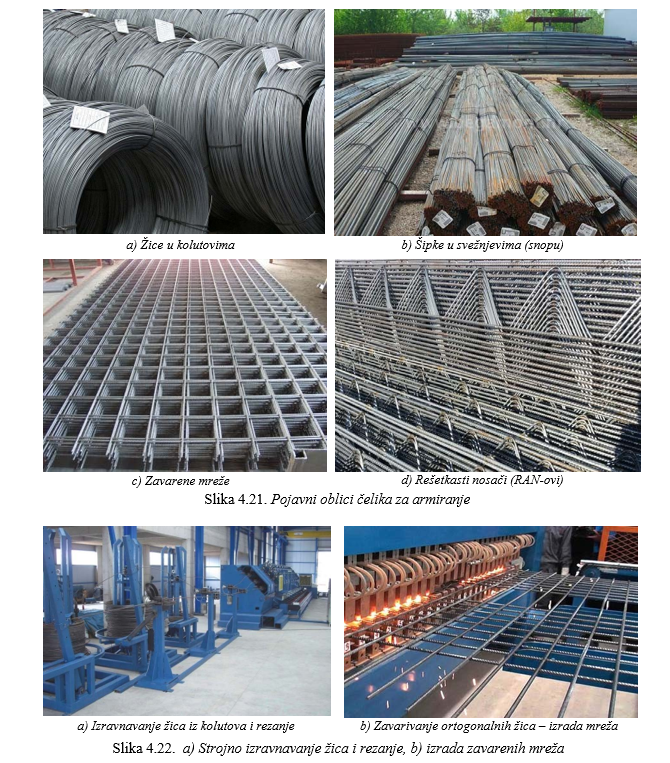
According to the apparent shape, the reinforcement steel is in the form of wire (f ≤ 12 mm), bars (f > 12 mm), welded meshes, and welded grids (Figure 4.21). Bars with a diameter f > 12 mm are usually delivered in a straight state in the form of bundles, usually with a length suitable for transport of 12 - 16 m. Thinner bar profiles can be delivered in the form of a coil, where the bars are 36 - 42 m long. Wires with a diameter f ≤ 12 mm are usually delivered in coils with a wire length of 36 - 42 m. Before use, the wire needs to be straightened, usually mechanically, as shown in Figure 4.22.-a. Welded meshes are made from cold-drawn wires by first mechanically straightening and positioning the wires in two parallel and mutually perpendicular planes, and then joining them by electric resistance welding (Figure 4.22.-b). Steel grids for reinforcement are made in a similar way.
Firstly, the property of bars and wires is their size. As their cross-section is regularly round, the characteristic of size is the nominal diameter of the bar (e.g. f6, f8, ... f32) by which the nominal cross-sectional area, net linear mass of the bar and other values related to various properties are calculated. Nominal diameters and cross-sectional areas are given in Table 4.12.

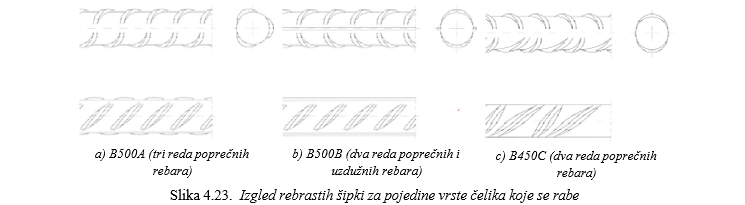
According to the surface features of the rod and wire, they are divided into smooth, ribbed (profiled) and notched (toothed). Ribbed and notched surfaces are made for better adhesion to concrete. According to the current standard, smooth and notched wires are used only for the production of welded meshes, while rebars are used exclusively for all other purposes. Also, the standard defines the appearance of the ribs for each class of rebars, which is shown in Figure 4.23, and it is also important for recognizing the quality of the embedded reinforcement.
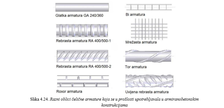
In the past, various types of rods were used for reinforcing concrete structures. A representation of the most commonly used reinforcement rods, which can be encountered in the reconstructions of existing buildings, is shown in Figure 4.24.
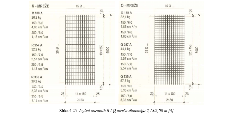
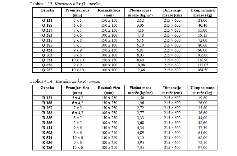
As already mentioned, reinforcement meshes are obtained by electro-welding wires placed one on top of the other in a mutually perpendicular position. The most common dimensions of reinforcement meshes produced today are 2.15/5.00 m and 2.15/6.00 m. The dimensions are mainly conditioned by transport (width of the mesh < width of a truck - 2.50 m) and installation (weight must be such that it can be manually carried). Meshes of the same wires and the same spacing in two perpendicular directions are called Q-meshes (from German Quadrat - square). Meshes with larger wires and smaller spacing in the direction of the longer dimension and smaller wires in the transverse (perpendicular) direction are called R-meshes (from German Rechteck - rectangle). Q-meshes are placed in slabs (and walls) that they support in two perpendicular directions, while R-meshes are placed in slabs (and walls) that they support in one direction, so that the bars with a larger diameter are placed in the direction of support. The appearance of Q and R meshes is shown in Figure 4.25. As a rule, in the name of the mesh, in addition to the type, there is a number that indicates the area of the steel bars in the support direction, expressed in mm2 per 1m width of the mesh. For example, the designation Q-335 means that the mesh has wires of diameter and spacing such that the area per 1m width of the mesh is equal to As = 335 mm2/m = 3.35 cm2/m. The usual types of Q and R meshes used in practice are shown in Tables 4.13 and 4.14.